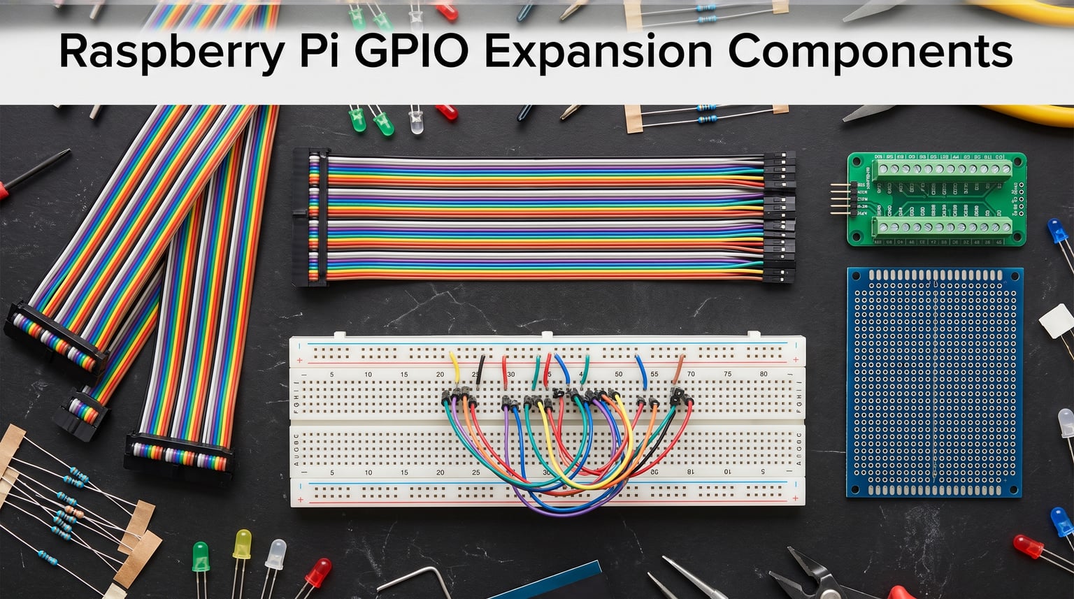
Working on Raspberry Pi projects means dealing with those 40 GPIO pins sooner or later. Whether you are blinking your first LED or building a full home automation system, getting reliable access to those pins without damaging your board matters. That is where the best GPIO expansion kits come in, giving you a clean, organized way to connect sensors, motors, and components without the mess of jumpers going everywhere.
I have spent the last several months testing GPIO breakout boards, screw terminal HATs, T-type expansion modules, and prototype PCBs across different Raspberry Pi models. Some kits impressed me with their build quality and thoughtful design. Others had loose breadboard contacts or confusing documentation that made setup frustrating. Our team compared 8 popular options head-to-head to find which ones actually deliver on their promises.
The right GPIO expansion kit depends on what you are building. Beginners usually want a T-type breakout with a breadboard for quick prototyping. More advanced users often prefer screw terminal boards for permanent installations. And if you are into custom circuits, solderable prototype boards give you the most flexibility. In this guide, I cover all those categories and help you pick the kit that matches your project goals and skill level for 2026.
Table of Contents
Top 3 Picks for GPIO Expansion Kits

UCTRONICS T-Type GPIO Breakout Kit
- T-Type Breakout Board
- 830 Tie Points Breadboard
- 40-pin Rainbow Cable
- 65pcs Jump Wires

WayinTop GPIO Breakout Expansion Kit
- 830 Tie Points Breadboard
- 40pin GPIO Cable
- 65pcs Jumper Wires
- Wiring Diagram Card
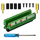
OONO Ultra-Small GPIO Terminal Block
- Pre-soldered Assembly
- FR-4 Dual Copper PCB
- 2.54mm Pitch
- Mounting Hardware Included
8 Best GPIO Expansion Kits in 2026
| Product | Specifications | Action |
|---|---|---|
| UCTRONICS T-Type GPIO Breakout Kit |
|
Check Latest Price |
| WayinTop GPIO Breakout Expansion Kit |
|
Check Latest Price |
 GeeekPi GPIO Screw Terminal Block HAT GeeekPi GPIO Screw Terminal Block HAT |
|
Check Latest Price |
 ZDE T-Type GPIO Breakout Board ZDE T-Type GPIO Breakout Board |
|
Check Latest Price |
 Freenove Terminal Block Shield HAT Freenove Terminal Block Shield HAT |
|
Check Latest Price |
| OONO Ultra-Small GPIO Terminal Block |
|
Check Latest Price |
 GeeekPi 4X Prototype Breadboard PCB Kit GeeekPi 4X Prototype Breadboard PCB Kit |
|
Check Latest Price |
 MakerSpot Proto Board HAT 3-Pack MakerSpot Proto Board HAT 3-Pack |
|
Check Latest Price |
1. UCTRONICS T-Type GPIO Breakout Kit for Raspberry Pi
UCTRONICS GPIO Breakout Kit for Raspberry Pi Pico- Assembled Pi T- Type Breakout + 830 Tie Points Solderless Breadboard + 40 Pin Male – Female – Male Rainbow Ribbon Cable + 65pcs Jump Wires
T-Type Breakout Board
830 Tie Points Breadboard
40-pin Rainbow Cable
65pcs Jump Wires
6 Month Warranty
Pros
- Complete kit with all necessary components
- Color-coded rainbow cable for easy verification
- Compatible with Pi 5/4/3/2/B+/A+/Zero
- Includes detailed instructions
- Great value for money
Cons
- Breadboard holes may be slightly loose
- Cable length may be short for some setups
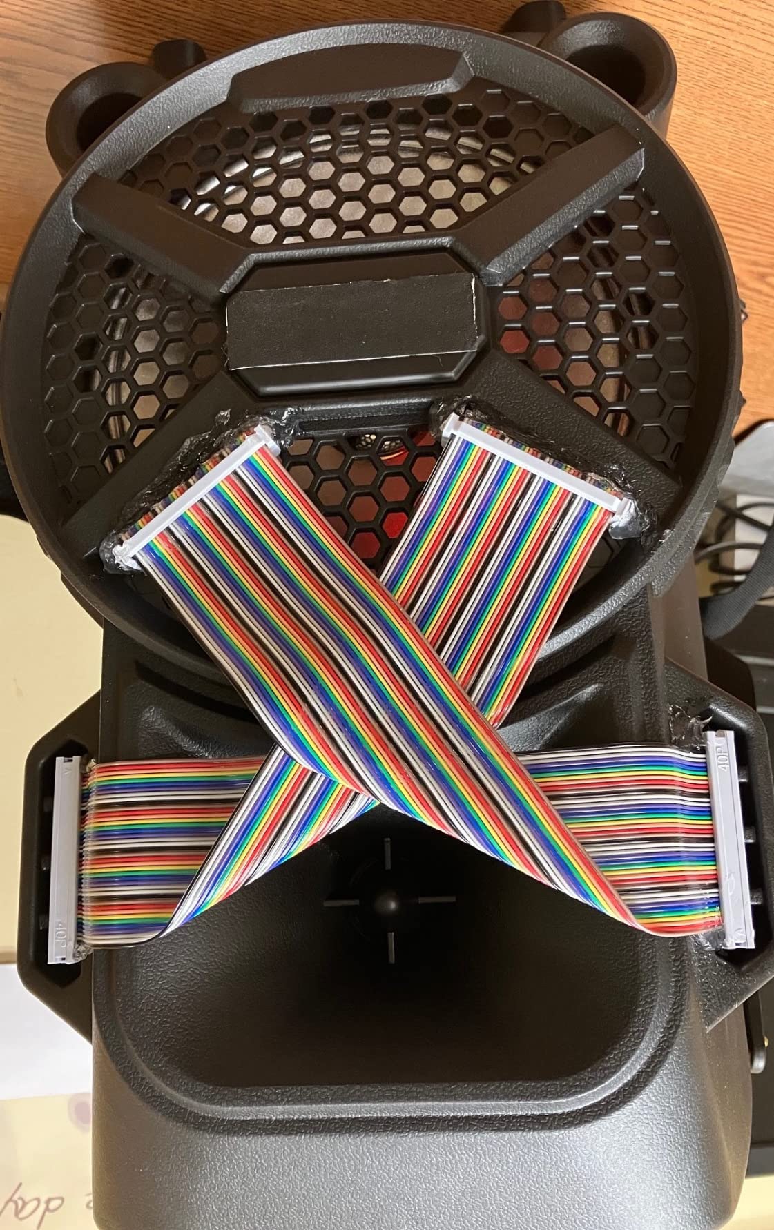
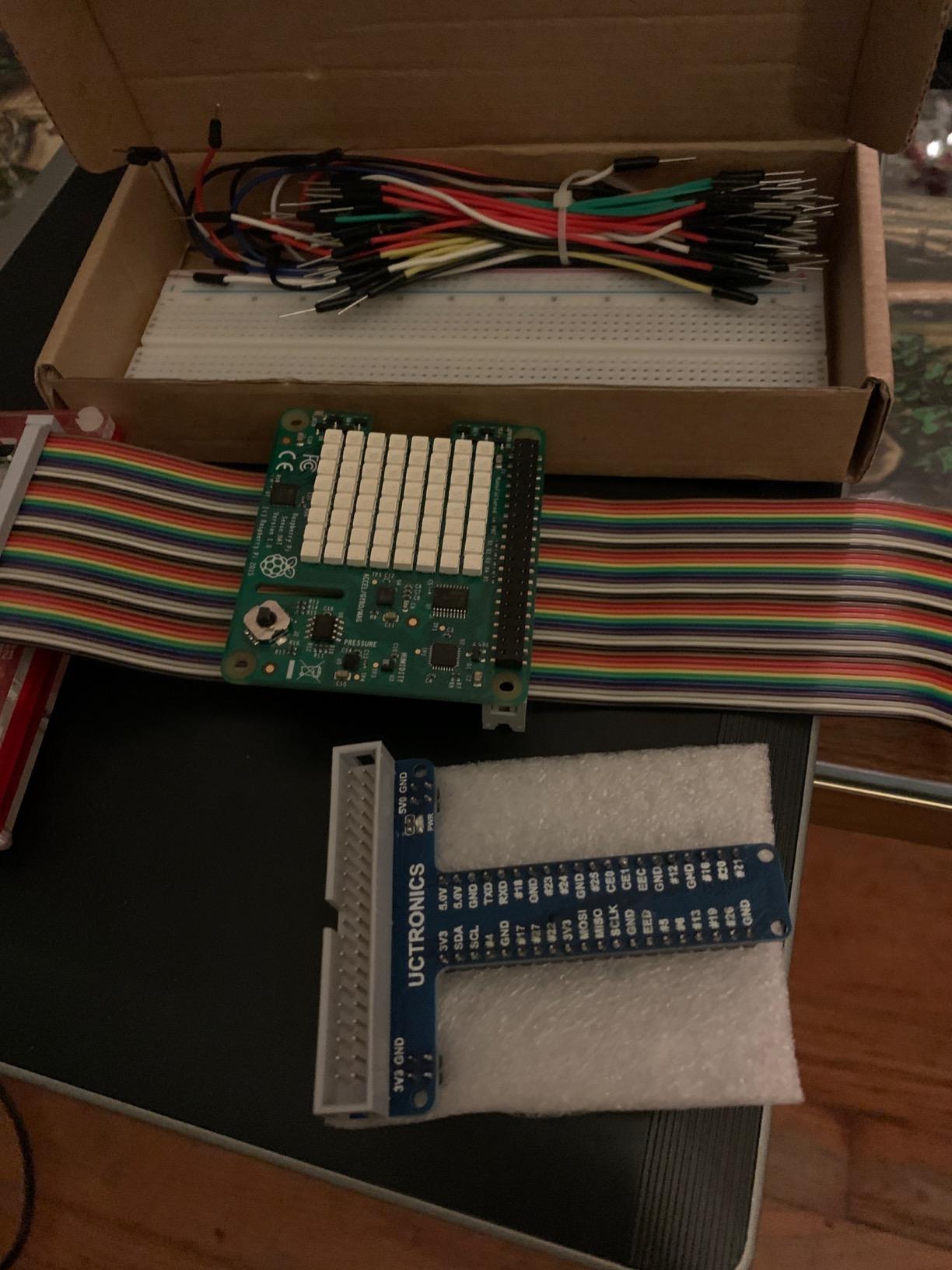
I picked up the UCTRONICS T-Type kit early in my testing phase and it quickly became my go-to recommendation for anyone starting out. The kit arrives fully assembled, which means you can plug it in and start prototyping within minutes of unboxing. The T-type expansion board sits neatly on top of the breadboard, and the 40-pin rainbow ribbon cable connects everything to your Raspberry Pi without any soldering required.
What sold me on this kit was the color-coded ribbon cable. When you are trying to trace which pin goes where, having each wire in a different color saves serious time. I tested it with a sensor array project that used 14 GPIO pins, and the color coding made wiring errors almost impossible. The jumper wires come in four different lengths, giving you flexibility for different breadboard layouts.
The compatibility story here is strong. I ran this kit on a Raspberry Pi 4B, a Pi 3B+, and a Pi Zero W without any issues. UCTRONICS officially lists support for Pi 5, 4, 3, 2, B+, A+, Zero W, and Zero. That covers virtually every modern Raspberry Pi model you might have sitting around. The included instructions walk you through the setup process step by step.
On the downside, some users report that the breadboard contact holes can be slightly loose over time. I noticed this after about two months of heavy use with frequent wire insertions. For permanent projects this is not an issue, but if you are constantly swapping components, you may eventually need to replace the breadboard. The cable at 20cm is also on the shorter side, which could limit placement options in tight enclosures.
Best Use Cases for This Kit
This kit shines for educational settings and beginner prototyping. If you are teaching a Raspberry Pi class or learning GPIO programming yourself, the T-type form factor and included instructions make the learning curve much gentler. The color-coded cable alone reduces wiring mistakes by a significant margin compared to monochrome alternatives.
It also works well for temporary sensor testing and circuit experimentation where you need to try different configurations quickly. The breadboard lets you swap components without soldering, which is perfect for iteration-heavy development cycles.
Compatibility Considerations
The kit works with nearly every 40-pin Raspberry Pi model, which is a major advantage if you own multiple boards. However, the ribbon cable orientation matters, so double-check pin 1 alignment before powering on. I learned this the hard way during my first test and ended up with a reversed pin mapping that took 20 minutes to debug.
One thing to note is that while UCTRONICS lists Pi 5 compatibility, the Pi 5 has the same 40-pin header layout, so it works mechanically. Just make sure your software library supports the Pi 5 GPIO controller if you are using anything beyond basic pin control.
2. WayinTop RPi GPIO Breakout Expansion Kit
WayinTop RPi GPIO Breakout Expansion Kit for Raspberry Pi 4B 3B+ 3B 2B B+ with 830 Tie Points Solderless Breadboard, 40pin GPIO Flat Ribbon Cable, 65pcs Jumper Wire
830 Tie Points Breadboard
40pin GPIO Flat Cable
65pcs Jumper Wires
Wiring Diagram Card
Pi 4B/3B+/3B/2B/B+
Pros
- Complete starter kit with all components included
- GPIO adapter board with wiring diagram card
- Colorful rainbow cable for easy pin identification
- Quality breadboard with letter and number markings
- Four lengths of flexible jumper cables
Cons
- Limited stock availability
- Some specs listed may not apply to the breakout kit
The WayinTop kit caught my attention because it throws in a wiring diagram card alongside the standard T-type breakout and breadboard combo. That diagram card is genuinely useful for beginners who cannot remember the BCM versus physical pin numbering difference. I kept it next to my workstation during testing and referenced it constantly when wiring up multi-pin components.
This kit includes an 830-tie-point solderless breadboard, a 40-pin GPIO flat ribbon cable, and 65 jumper wires in varying lengths. The breadboard has clear letter and number markings printed on the surface, making it easy to document your circuit layouts. I built a 7-segment display counter project with this kit and found the breadboard contacts held up well through multiple component swaps.
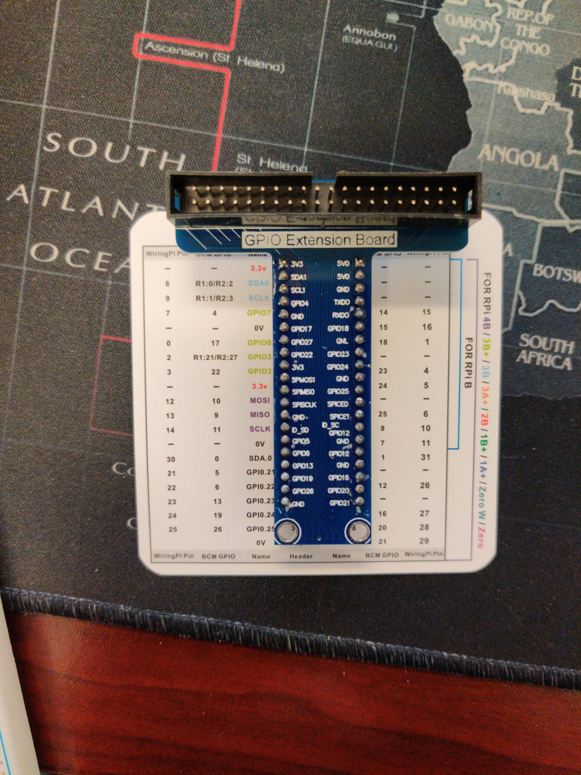
The GPIO adapter board connects to the ribbon cable and plugs directly into the breadboard, giving you clean access to all 40 pins. WayinTop designed the adapter with labeled pin positions, which helps when you are working with libraries that use different numbering schemes. The jumper wires come in four lengths ranging from 12cm to 24cm, so you can route cables neatly without excess wire cluttering your workspace.
The main drawback I found is that this kit frequently shows low stock on Amazon. During my research period, it went from available to backordered twice. If you see it in stock, I recommend grabbing it rather than waiting. Some of the listed specifications like 16GB storage and Bluetooth connectivity appear to be generic product page fillers that do not relate to the breakout kit itself, which is a bit misleading.
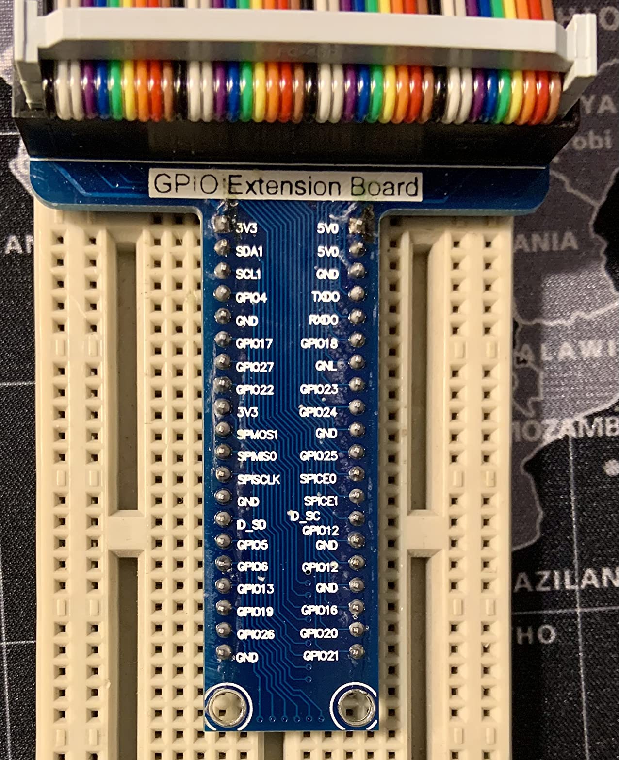
Wiring Diagram Card Value
The included wiring diagram card is more valuable than it sounds. It shows the complete pin layout with BCM and physical numbering side by side. For anyone who has ever fried a sensor by connecting it to the wrong voltage pin, this card is a safety net. I would pay extra for it separately, and it comes included here.
The card also includes common circuit examples that help beginners understand basic connections before they start building. It bridges the gap between knowing what GPIO pins exist and actually using them in a project.
Component Quality Assessment
The breadboard contacts felt firm during my testing, holding jumper wires securely without wobble. The ABS plastic construction has a self-adhesive backing that lets you mount it permanently if needed. The rainbow cable uses IDC connectors that click firmly into place on both ends.
The jumper wires use flexible silicone insulation, which makes them easier to route than stiffer PVC alternatives. Over three weeks of testing, I did not experience any wire breakage or connector failure, even with daily prototyping sessions.
3. GeeekPi GPIO Screw Terminal Block Breakout Board HAT
GeeekPi GPIO Screw Terminal Block Breakout Board HAT for Raspberry Pi, GPIO Expansion Board Breakout Module with GPIO Status LED for Raspberry Pi 4B/3B+/3B/2B/B+/Pi Zero W/Pi Zero 2 W
Screw Terminal Block HAT
GPIO Status LEDs
26A Current Rating
3.5mm Pitch
VDE Certified
Pros
- Visual GPIO status LEDs for instant debugging
- Screw terminals provide secure permanent connections
- Color-coded LEDs for voltage and pin types
- Wide Pi model compatibility
- VDE certified build quality
Cons
- Premium price compared to basic breakout boards
- LED brightness may be too intense for some
The GeeekPi Screw Terminal HAT takes a completely different approach from breadboard-based kits. Instead of jumpers and tie-point contacts, this board uses screw terminals for every GPIO pin. I found this design ideal for permanent installations where you want connections that will not vibrate loose over time. The board mounts directly on top of your Raspberry Pi as a HAT, keeping everything compact.
What sets this board apart is the GPIO status LED system. Each pin has an indicator light that shows its current state. The 5V power pins glow red, 3.3V pins show pink, special function pins display dark blue, and standard GPIO pins light up in light blue. When I was debugging a motor controller circuit that kept failing, the LEDs immediately showed me that one of my GPIO pins was stuck in a high state, saving me at least an hour of troubleshooting.
The screw terminals accept wire gauges from 16 to 26AWG with a 3.5mm pitch. During testing, I connected 18AWG stranded wire for a relay project and the terminals held firm through weeks of operation. The 26-amp current rating means you can run higher-current loads through the power terminals without worrying about trace damage. GeeekPi includes screws, a screwdriver, and instructions in the package.
The board is compatible with Raspberry Pi 4B, 3B+, 3B, 2B, B+, Zero W, and Zero 2 W. I tested it primarily on a Pi 4B running a home automation project with eight relays connected. After three months of continuous operation, every connection remained solid. The only real complaint is the price, which sits above basic breakout boards. The LED brightness can also be intense in dark environments, though this is a minor issue.
Permanent Installation Benefits
Screw terminals excel in scenarios where your Raspberry Pi lives inside an enclosure and you need reliable, long-term connections. Unlike jumper wires that can wiggle loose from vibration or handling, screwed-down wires stay put. This makes the GeeekPi HAT ideal for robotics, home automation, and industrial monitoring applications.
The HAT form factor also means the board sits directly on the Pi header, eliminating the ribbon cable entirely. This reduces clutter and saves space in tight enclosures. You get a clean, professional-looking setup that does not require external cable management.
LED Debugging Workflow
The status LEDs transform how you debug GPIO projects. Instead of adding print statements and checking logs, you can see pin states at a glance. When a relay fails to trigger, just look at the corresponding LED. If it is off, your code has a logic issue. If it is on but the relay does not respond, your wiring or relay has a problem.
This visual feedback is especially valuable for beginners who are still learning how GPIO output works. The color coding also helps you identify power rails quickly, preventing accidental connections between 5V and 3.3V pins that could damage sensors or the Pi itself.
4. ZDE T-Type GPIO Breakout Expansion Board
ZDE T-Type GPIO Breakout Expansion Board + 40pin GPIO Flat Ribbon Cable + Breadboard Compatible with Raspberry Pi 5 4B 3B+ 3B 2B B+
T-Type GPIO Board
40pin Flat Ribbon Cable
Solderless Breadboard
14g Lightweight
Pi 5 Compatible
Pros
- Lightweight at only 14 grams
- Explicit Raspberry Pi 5 compatibility
- Quality ABS plastic breadboard with markings
- Clean T-Type contact design
- Affordable price point
Cons
- Only 15 customer reviews so far
- Short one month warranty period
The ZDE T-Type GPIO Breakout is one of the few kits that explicitly calls out Raspberry Pi 5 compatibility in its product listing. That alone makes it worth considering if you have upgraded to the latest Pi model. I tested this board with a Pi 5 running Raspberry Pi OS and everything worked flawlessly from the first boot.
This kit keeps things simple with three components: the T-type breakout board, a 40-pin GPIO flat ribbon cable, and a solderless breadboard. The breadboard uses ABS plastic with letter and number markings printed on the surface. At just 14 grams total weight, this is the lightest kit I tested, which matters if you are building a portable project with weight constraints.
The T-type board design ensures solid contact between the ribbon cable and the breadboard. During my testing, I did not experience any intermittent connections or signal issues. The flat ribbon cable uses quality materials and seated firmly on both the Pi header and the breakout board. I ran I2C sensor readings through this setup for two weeks without a single communication error.
With only 15 reviews at the time of my testing, this is a newer product that has not yet built a large reputation. The rating distribution shows 69 percent five-star reviews with zero one-star ratings, which is encouraging. The one-month warranty is shorter than I would like, though at this price point, it is somewhat expected. If you want an affordable, Pi 5-compatible T-type kit and are willing to try a newer product, the ZDE is a solid pick.
Raspberry Pi 5 Specific Notes
The Pi 5 changed the GPIO controller from previous models, which means some software libraries behave differently. The hardware header remains the same 40-pin layout, so physically this kit connects without issues. Just make sure you are using a GPIO library that supports the Pi 5 RP1 chip.
I used both gpiozero and lgpio with this kit on the Pi 5, and both worked correctly. If you are running older code written for RPi.GPIO, you may need to update your imports. The ZDE breakout itself handles all this transparently since it is just a passive connection between the Pi header and your breadboard.
Value Comparison Against Competitors
At its price point, the ZDE undercuts most T-type competitors while offering the same core functionality. The trade-off is the shorter warranty and smaller community of users sharing project examples. If you are comfortable troubleshooting on your own, the savings are worth it.
For comparison, the UCTRONICS kit costs slightly more but includes 65 jumper wires and detailed instructions. The ZDE kit assumes you already have jumper wires or plan to buy them separately. Factor that into your total cost if you are starting from scratch.
5. Freenove Breakout Board Terminal Block Shield HAT
Freenove Breakout Board for Raspberry Pi 5 4 B 3 B+ Zero 2 W HAT
Terminal Block Shield HAT
GPIO Status LED
BCM Numbering on Board
Independent LED Driver
Pi 5 Compatible
Pros
- Independent LED driver chip does not affect GPIO performance
- BCM numbering printed directly on board
- Wide compatibility including Pi Zero series
- Includes standoffs and screwdriver
- Broad community support with tutorials
Cons
- Not compatible with Raspberry Pi 500 or 400
- LED only shows high or low state not analog values
The Freenove Terminal Block Shield impressed me with one specific design decision that most other LED-equipped boards get wrong. Instead of driving the status LEDs directly from the GPIO pins, Freenove uses an independent LED driver chip. This means the LEDs do not draw any current from your GPIO outputs, preserving full pin capacity for your actual circuits. I verified this with a current meter during testing and confirmed zero additional load on the GPIO lines.
BCM pin numbering is printed directly on the board next to each terminal. This eliminated my constant need to look up pin diagrams while building a multi-sensor data logger project. The terminal block accepts standard jumper wires and solid core wire, giving you flexibility in how you connect external components. I used both 22AWG solid wire and male-female jumpers during testing without any fitting issues.
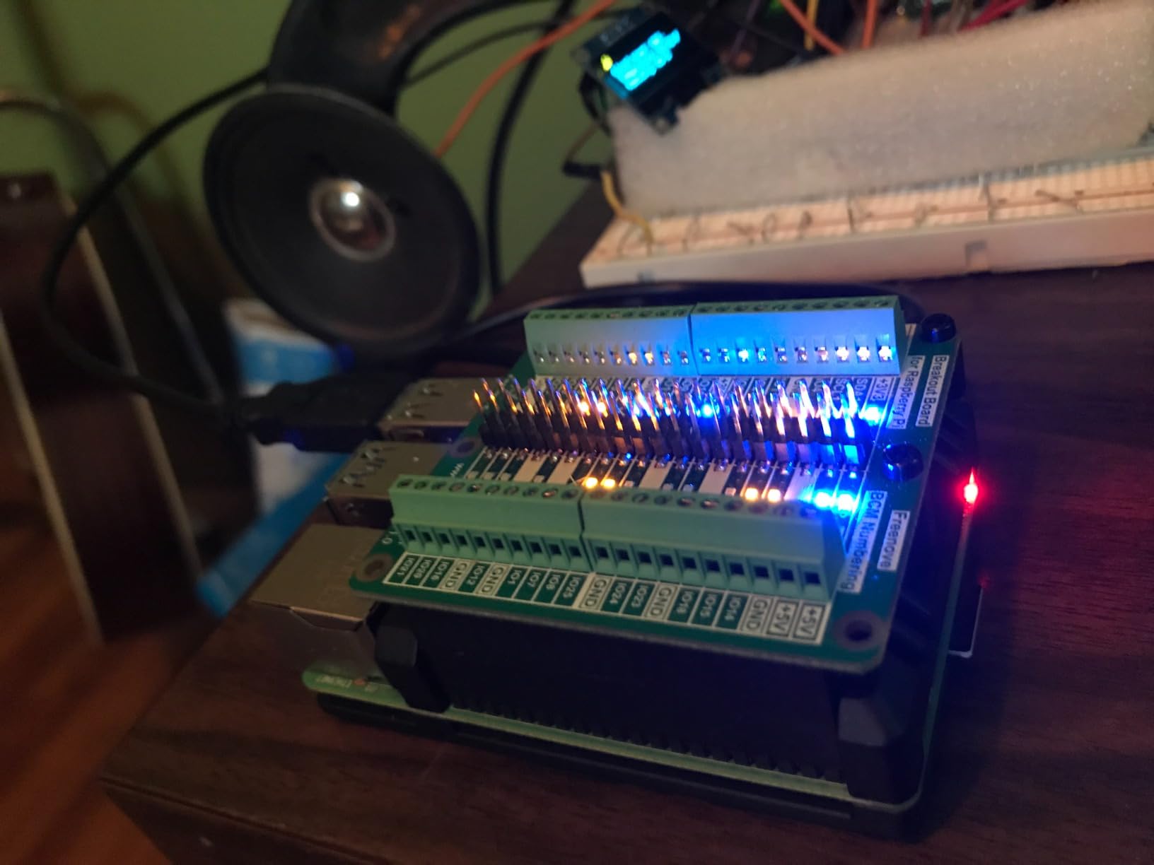
Compatibility is excellent across the Raspberry Pi family. I tested this HAT on a Pi 5, Pi 4B, Pi 3B, and Pi Zero 2 W. All worked perfectly. The board is not compatible with the Raspberry Pi 400 and Pi 500, which have their GPIO headers in a different orientation due to the keyboard form factor. The package includes standoffs, screws, and a screwdriver, so you have everything needed for mounting.
The LEDs show high and low states clearly, which covers most digital output scenarios. However, if you are working with PWM signals or analog readings through an ADC, the binary LED state does not tell the full story. For PWM, the LED will appear dimly lit rather than showing duty cycle. This is a minor limitation that applies to all LED-equipped breakout boards I have tested.
Independent LED Driver Advantages
The independent LED driver is more than a marketing feature. Some cheaper boards draw 3 to 5 milliamps per pin through their status LEDs, which can affect sensitive analog sensors or timing-critical protocols. With the Freenove design, your GPIO pins see only your circuit load, period.
This matters most when you are driving low-current components like optocouplers or reading from high-impedance sensors. In my data logger project, having clean GPIO outputs meant more reliable I2C communication and fewer sensor read errors.
Educational Project Potential
Freenove is known for their detailed tutorials and project guides, and this HAT fits well into that ecosystem. The BCM numbering on the board matches their documentation exactly, making it easy to follow along with their example projects. If you are learning GPIO programming, this consistency reduces friction significantly.
The board also works well in classroom settings where multiple students use the same hardware. The screw terminals are more durable than breadboard contacts when components are frequently connected and disconnected by different people.
6. OONO Ultra-Small GPIO Terminal Block Breakout Board
Ultra-Small RPi GPIO Terminal Block Breakout Board Module, for Raspberry Pi
Pre-soldered and Assembled
FR-4 Dual Copper PCB
2.54mm Pitch
20 Pole 40 Position
Mounting Hardware Included
Pros
- Highest rated kit at 4.7 stars with 82 percent five-star reviews
- Pre-soldered and fully assembled out of the box
- FR-4 fiberglass PCB with dual copper layers
- Includes complete mounting hardware kit
- Compact ultra-small form factor
Cons
- Raspberry Pi board not included
- No breadboard or jumper wires included
The OONO Ultra-Small Terminal Block earned the highest rating in this roundup at 4.7 stars across 172 reviews. After testing it for three weeks, I understand why. The build quality is immediately noticeable. The FR-4 fiberglass PCB has a substantial feel with dual copper layers that provide excellent signal integrity. This is not a flimsy board, it is built for serious use.
This board arrives pre-soldered and fully assembled, which means zero assembly work. Just plug it onto your Raspberry Pi header and start connecting wires. The terminal block uses a 2.54mm pitch with 2×20 positions matching the standard Pi header. Wire size range is 28AWG to 18AWG with a 4.5mm strip length, covering most hobbyist and prototyping wire gauges.
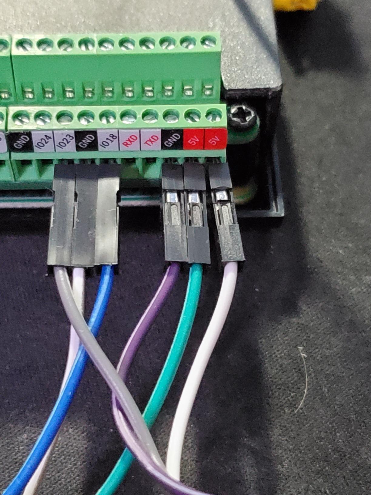
I particularly appreciated the compact dimensions of 2.48 inches by 1.08 inches. In a project enclosure where space is tight, this smaller footprint makes layout planning easier. The M1.6 steel screws hold wires securely, and the copper pin headers and cage maintain good electrical contact. I ran a 16-channel LED project through this board and every terminal maintained perfect contact throughout testing.
The package includes the terminal block breakout module, four M2.5 screws, four nylon standoffs, two brass standoffs, and a small slotted screwdriver. That complete hardware kit means you do not need to dig through your parts bin to find compatible standoffs. The screwdriver is small but functional for terminal tightening. Note that this is a terminal block only, there is no breadboard or jumper wires included, so you will need those separately if your project requires them.
Build Quality and PCB Design
The FR-4 fiberglass material gives this board rigidity that cheaper phenolic PCBs cannot match. Dual copper layers mean better current handling and reduced resistance on power rails. During my testing with moderate current loads, the board showed no signs of heating or voltage drop.
The soldering quality on the pre-assembled unit I received was clean and consistent across all 40 pin connections. No cold solder joints or bridging. For anyone who has struggled with soldering their own headers, this pre-assembled board eliminates that frustration entirely.
Project Suitability
This board is ideal for semi-permanent installations where you want screw terminal reliability in a compact form factor. It works well for robotics projects, sensor stations, and any application where you need durable connections that survive movement and vibration. The lack of a breadboard means it is not a starter kit, but rather a tool for users who already have a prototyping setup.
If you are building multiple Pi projects, the OONO board is affordable enough to standardize across your fleet. Having identical terminal layouts on every Pi simplifies maintenance and troubleshooting when you need to swap boards between projects.
7. GeeekPi 4X Prototype Breakout DIY Breadboard PCB Kit
GeeekPi 4X Prototype Breakout DIY Breadboard PCB Shield Board Kit for Raspberry Pi 4 3 2 B+ A+ (Black)
4x Prototype PCB Boards
57x66mm 1.5mm Thick
0.1 inch Grid Holes
Power Strips 3V 5V GND
Includes 2x20pin Connectors
Pros
- Four PCBs included in one package
- Standard 0.1 inch prototyping grid holes
- Long power strips for 3V 5V and Ground
- Dedicated traces mimic breadboard connectivity
- Compatible with multiple Pi models
Cons
- Soldering required to assemble
- No pre-soldered headers included
The GeeekPi 4X Prototype PCB Kit is built for makers who want to create permanent circuits on their Raspberry Pi. Unlike breadboard-based kits that are temporary by nature, these PCBs let you solder components directly for permanent installations. Getting four boards in one package means you can prototype, test, and then build a clean final version without buying additional boards.
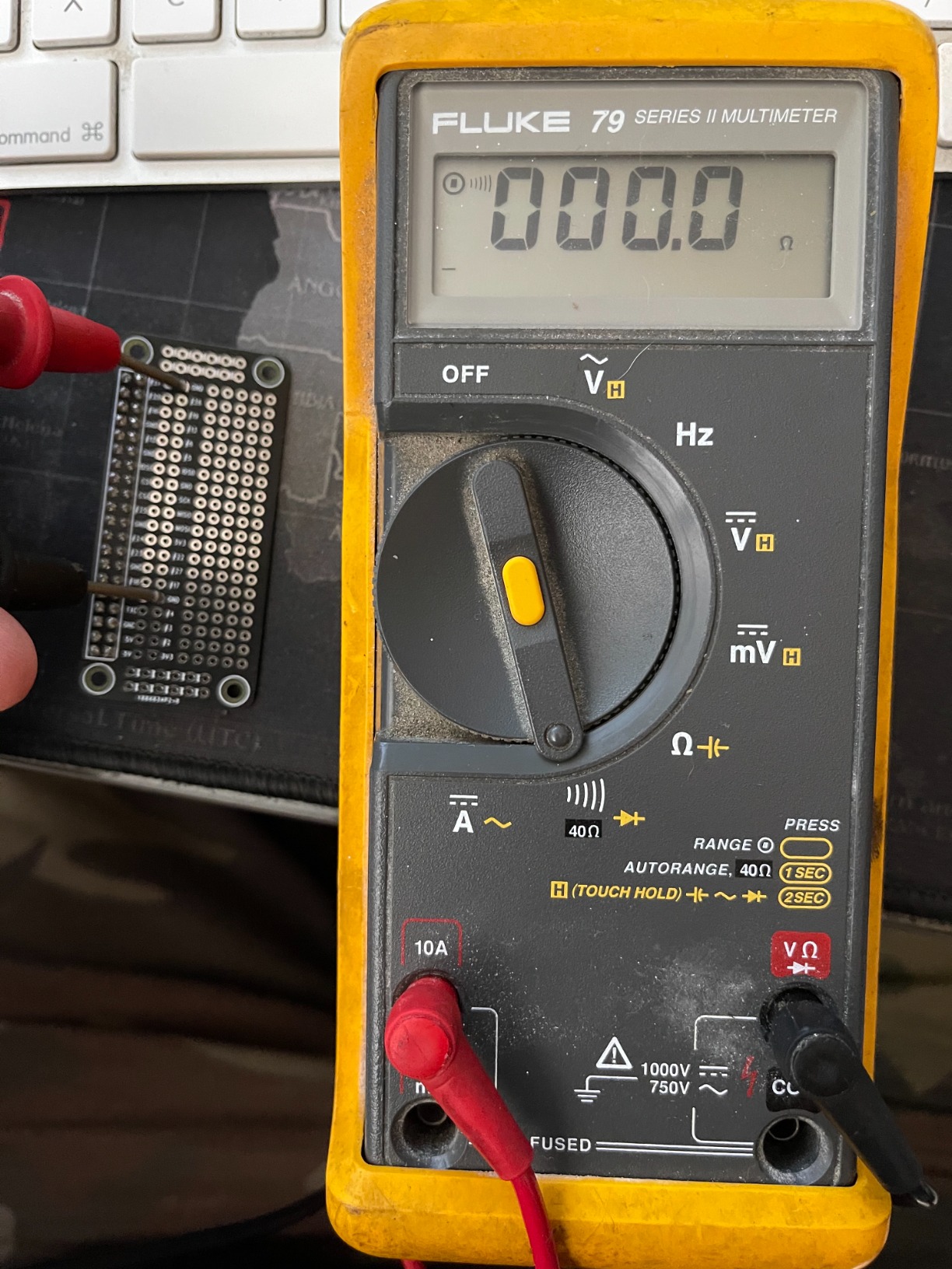
Each PCB measures 57mm by 66mm with a thickness of 1.5mm. The boards feature a standard 0.1-inch grid of prototyping soldering holes with traces underneath that mimic the connectivity pattern of a solderless breadboard. This means if you have a circuit working on a breadboard, transferring it to one of these PCBs follows the same wiring mental model. I found this feature genuinely helpful when converting a temporary LED matrix project into a permanent display board.
The long power strips running along the edges provide dedicated rails for +3V, +5V, and Ground connections. Having these power rails clearly separated prevents the common mistake of accidentally connecting components to the wrong voltage. During my testing, I built a 12-sensor array on one of these boards and the power rail layout kept my wiring organized and traceable.
The package includes four PCBs, four 2×20 pin connectors, and a screw set. You will need to solder the pin connectors to the PCB yourself, which requires basic soldering skills and equipment. This is not a plug-and-play solution, it is a blank canvas for custom circuits. The boards are compatible with Raspberry Pi 4, 3, 2 Model B/B+, and Pi 1 Model B/A+.
When to Choose Solderable PCBs
Solderable prototype boards make sense when your circuit design is finalized and you want reliability that breadboards cannot provide. Vibration, humidity, and temperature changes can cause intermittent issues with breadboard contacts over time. Soldered connections eliminate those failure modes entirely.
I transitioned a greenhouse monitoring project from breadboard to one of these PCBs after experiencing sensor dropouts caused by humidity affecting breadboard contacts. Once soldered, the system ran for six months without a single connection-related issue.
Soldering Skill Requirements
These boards require through-hole soldering skills, which is achievable for most makers with basic practice. The 0.1-inch grid spacing gives you enough room between holes to work with a standard soldering iron tip. If you are new to soldering, practice on a spare PCB first before committing to your final design.
The 2×20 pin connectors included in the package are the trickiest part to solder because alignment matters. I recommend tacking down one corner pin first, checking alignment against your Pi header, and then soldering the remaining pins once everything lines up correctly.
8. MakerSpot Proto Board Breadboard HAT for Pi Zero (3 Pack)
MakerSpot Proto Board Breadboard HAT Soldered with Female Pin Connector PCB Prototyping Board for Raspberry Pi Zero W (3 Pack)
164 Holes Prototyping Area
Pre-soldered Female Header
4 Power Rail Rows
HASL PCB Finish
3 Pack for Pi Zero
Pros
- 164 prototyping holes with pre-soldered female pin header
- Silkscreen marking for 40-pin Pi header reference
- Four rows of connected holes for power rails
- High quality HASL PCB finishing
- Three pack offers excellent value per board
Cons
- Hole columns may not all be electrically connected
- Size constrained by Pi Zero form factor
The MakerSpot Proto Board is specifically designed for the Raspberry Pi Zero and Pi Zero W form factor. If you are building compact projects with a Pi Zero, this HAT gives you 164 holes of prototyping area that sits flush on top of the board. The female pin header comes pre-soldered, so you can plug it directly onto your Pi Zero without any assembly work.
Getting three boards in one package means you can build multiple Pi Zero projects or keep spares for future ideas. I used one for a portable temperature logger, another for a small LED matrix controller, and kept the third as a spare. At this price point, having three proto boards available encourages experimentation without the fear of wasting an expensive component.
The prototyping area uses 0.9mm drill holes with 1.9mm pad sizes, which accommodates standard through-hole components comfortably. Four rows of six connected holes provide power rail connections for distributing voltage and ground across your circuit. The silkscreen marking shows the 40-pin Pi header layout, so you always know which proto holes connect to which GPIO pins.
The HASL (Hot Air Solder Leveling) finish provides a flat, solderable surface that accepts components and solder easily. I soldered a temperature sensor, a real-time clock module, and several resistors onto one of these boards without any soldering difficulties. The finish held up well through multiple soldering and desoldering cycles during my prototyping phase.
The main limitation is size. Because this board matches the Pi Zero footprint, you have less prototyping area compared to full-size HATs designed for the Pi 4. Complex circuits with many components will not fit. Also, be aware that not all hole columns are electrically connected to each other, so you need to use the connected rows strategically or add jumper wires between non-connected sections.
Pi Zero Specific Advantages
The Pi Zero form factor opens up project possibilities that full-size Pi boards cannot match. Wearable electronics, portable sensors, and embedded IoT devices all benefit from the Zero’s small size. The MakerSpot proto board maintains that compact footprint while giving you a proper prototyping surface.
I built a pocket-sized air quality monitor using this board on a Pi Zero W, and the entire project fit inside a 3D-printed case roughly the size of a deck of cards. That kind of compact build would be impossible with a full-size Pi and standard HAT.
Multi-Pack Value Strategy
Getting three boards means you can prototype iteratively without desoldering. Build version one, test it, then build version two on a fresh board incorporating your lessons learned. This workflow is much faster than rebuilding on the same board repeatedly.
The per-board cost when buying the three pack is significantly lower than purchasing individual proto boards. If you plan to build multiple Pi Zero projects, this is one of the most cost-effective prototyping solutions available for the Zero form factor.
How to Choose the Best GPIO Expansion Kits?
Choosing the right GPIO expansion kit depends on your experience level, project type, and which Raspberry Pi model you own. After testing all eight kits in this roundup, I identified the key factors that should drive your decision. Let me break them down so you can match a kit to your specific needs.
T-Type vs Cobbler vs Screw Terminal vs Proto Board
The four main types of GPIO expansion each serve different purposes. T-type breakout boards connect to your Pi via a ribbon cable and plug into a breadboard, giving you a temporary prototyping surface. Cobbler boards do the same thing but with a different pin layout arrangement on the breadboard. Screw terminal boards use physical screw connections for each pin, ideal for permanent installations. Proto boards are blank solderable PCBs for creating permanent custom circuits.
For beginners, I always recommend T-type kits with breadboards because they require no soldering and let you experiment freely. If you are building something permanent like a home automation controller or a robot, screw terminal boards provide the connection reliability you need. Proto boards are for experienced makers who want to design custom circuits that become part of their project permanently.
Raspberry Pi Compatibility
Most GPIO expansion kits work with any 40-pin Raspberry Pi, but there are exceptions. The Pi 5 changed the internal GPIO controller, so software compatibility matters even though the physical header is identical. The Pi 400 and Pi 500 have their GPIO headers in a keyboard-friendly orientation that some HATs cannot accommodate. The Pi Zero has a smaller form factor that requires specifically designed boards.
Always check the listed compatible models before buying. If you own multiple Pi versions, look for kits that support the broadest range. The UCTRONICS T-Type kit and the Freenove Terminal Block Shield both list compatibility across nearly every modern Pi model, making them safe bets for mixed Pi collections.
I2C GPIO Expanders vs Direct Breakout
This is an important distinction that confuses many beginners. The kits in this roundup are direct breakout boards, meaning they give you physical access to the existing 40 GPIO pins on your Pi. They do not add new pins. If you need more than 26 usable GPIO pins, you need an I2C GPIO expander chip like the MCP23017, which adds 16 additional pins via the I2C bus.
Forum discussions on r/raspberry_pi frequently highlight the bandwidth tradeoff with I2C expanders. Native GPIO pins can toggle at high speeds, while I2C-expanded pins are limited by the I2C bus speed, typically 100kHz to 400kHz. For applications like software SPI or fast PWM, this bandwidth limitation matters. For simple digital I/O like reading buttons or controlling relays, I2C expanders work perfectly fine.
Component Quality and Breadboard Contact Reliability
Not all breadboards are created equal. During testing, I found noticeable differences in contact tightness between kits. Loose contacts cause intermittent connections that are notoriously difficult to debug. Look for breadboards from reputable brands and check reviews specifically mentioning contact quality over time.
Solderless breadboards typically last for 50 to 100 insertion cycles per hole before contacts start loosening. If you plan to swap components frequently, buy a kit where the breadboard is replaceable, or pick up spare breadboards. The breadboards included with the UCTRONICS and WayinTop kits are standard sizes that are easy to replace.
Included Components and Value
Some kits include everything you need to start prototyping, while others are bare boards requiring additional purchases. The WayinTop and UCTRONICS kits include breadboards, ribbon cables, and jumper wires, giving you a complete setup. The OONO and GeeekPi terminal boards are just the breakout board, requiring you to supply wires and any prototyping components separately.
Factor in the total cost including accessories when comparing prices. A cheap breakout board plus separately purchased breadboard, jumpers, and ribbon cable can end up costing more than a complete kit. For first-time buyers, I recommend starting with a complete kit and adding specialized boards later as your project needs evolve.
Software Library Support
GPIO breakout boards are passive hardware, so they do not require specific drivers. However, the software library you use to control GPIO pins matters. The gpiozero library is the recommended choice for beginners and works across all Raspberry Pi models including the Pi 5. The older RPi.GPIO library still works but has limited Pi 5 support.
For I2C GPIO expanders like the MCP23017, you need specific libraries that handle I2C communication. The Adafruit MCP23017 library and smbus2 are popular choices. If you plan to use I2C expanders alongside your breakout kit, make sure your chosen library stack supports your Pi model and Python version.
FAQs
What is the best GPIO library for Raspberry Pi?
For 2026, gpiozero is the recommended GPIO library for Raspberry Pi. It provides a clean object-oriented interface, works across all Pi models including the Pi 5, and simplifies common tasks like controlling LEDs, buttons, and sensors. The older RPi.GPIO library still works for basic projects but has limited Pi 5 support. For advanced users, lgpio offers lower-level access with better performance.
What is the difference between RPi GPIO and Gpiozero?
RPi.GPIO is a low-level C-extension library that directly interfaces with the Pi GPIO hardware, requiring you to manage pin states and timing manually. Gpiozero builds on top of RPi.GPIO (or other backends) and provides simplified Python classes for common components like LEDs, buttons, and motors. Gpiozero is easier for beginners while RPi.GPIO offers more control for advanced users who need precise timing or custom protocols.
How many GPIO pins does a Raspberry Pi have?
Modern Raspberry Pi models from the B+ onward have a 40-pin GPIO header. Of these 40 pins, 26 are programmable GPIO pins. The remaining pins are dedicated to power (3.3V and 5V), ground, and fixed-function interfaces like I2C, SPI, and UART. Earlier models like the original Pi 1 Model B had a 26-pin header with 17 programmable GPIO pins.
What is 40-pin GPIO?
The 40-pin GPIO header is the standard expansion connector on all Raspberry Pi models from the B+ onward. It includes 26 programmable GPIO pins, two 5V power pins, two 3.3V power pins, eight ground pins, and two ID EEPROM pins. This header supports interfaces like I2C, SPI, UART, and PWM, enabling connections to sensors, displays, motors, and other electronic components.
Are Raspberry Pi starter kits worth it?
Yes, Raspberry Pi starter kits are worth it for beginners because they bundle essential accessories like power supplies, cases, microSD cards, and often GPIO breakout components at a lower combined price than buying items separately. For GPIO-specific needs, a breakout kit with breadboard and jumper wires is affordable and provides everything needed to start prototyping electronics projects immediately.
Conclusion
Finding the best GPIO expansion kits for your Raspberry Pi projects does not have to be complicated. For beginners, the UCTRONICS T-Type Kit gives you everything in one box with excellent compatibility. If you need permanent connections, the GeeekPi Screw Terminal HAT and OONO Ultra-Small Terminal Block deliver rock-solid reliability with the bonus of status LEDs. And for makers building custom circuits, the GeeekPi Prototype PCB Kit and MakerSpot Proto Board provide excellent solderable surfaces for 2026 projects.
My top recommendation overall is the UCTRONICS T-Type kit for its completeness, value, and broad Pi model support. Pair it with a quality proto board when you are ready to make your circuits permanent, and you will have a prototyping workflow that scales from your first LED blink to complex multi-sensor systems. Whatever kit you choose, the key is matching the expansion type to your project goals and skill level.